Quantcast
Channel: Avid CNC
Viewing all 329 articles
Browse latest View live

PRO4824 - 4' x 2' Machine Plans

$
0
0
PRO4824 - 4' x 2' Machine Plans
CNC Router Parts is pleased to present machine plans for our new PRO4824 - 2' x 4' PRO CNC machine kit, which is now available for purchase!

The kits feature all mechanical components for a bolt-together machine, purchasable through CNC Router Parts, and ready to work with our easy-to-use Nema 23 or Nema 34 electronics, as well as those from other vendors should you choose.


Plans
Our latest plans are now available in eDrawings (EASM) and PDF format.For those not familiar, easm is a free 3D format that allows you to rotate, zoom, and take measurements off of the plans. To view the easm files, just download the free edrawings viewer. Download and enjoy!

Download Latest Plans, version 2013Q2.1:

New in: Machine Plans

PRO4848 - 4' x 4' Machine Plans

$
0
0
PRO4848 - 4' x 4' Machine Plans
CNC Router Parts is pleased to present machine plans for our new PRO4848 - 4' x 4' PRO CNC machine kit, which is now available for purchase!

The kits feature all mechanical components for a bolt-together machine, purchasable through CNC Router Parts, and ready to work with our easy-to-use Nema 23 or Nema 34 electronics, as well as those from other vendors should you choose.


Plans
Our latest plans are now available in eDrawings (EASM) and PDF format.For those not familiar, easm is a free 3D format that allows you to rotate, zoom, and take measurements off of the plans. To view the easm files, just download the free edrawings viewer. Download and enjoy!

Download Latest Plans, version 2013Q2.1:

New in: Machine Plans

PRO4896 - 4' x 8' CNC Machine Plans

$
0
0
PRO4896 - 4' x 8' CNC Machine Plans
CNC Router Parts is pleased to present machine plans for our new PRO4896 - 4' x 8' PRO CNC machine kit, which is now available for purchase!

The kits feature all mechanical components for a bolt-together machine, purchasable through CNC Router Parts, and ready to work with our easy-to-use Nema 23 or Nema 34 electronics, as well as those from other vendors should you choose.


Plans
Our latest plans are now available in eDrawings (EASM) and PDF format.For those not familiar, easm is a free 3D format that allows you to rotate, zoom, and take measurements off of the plans. To view the easm files, just download the free edrawings viewer. Download and enjoy!

Download Latest Plans, version 2013Q2.1:

New in: Machine Plans

Steel Leg Kit (PRO CNC)

$
0
0
Steel Leg Kit (PRO CNC)
Our 14 gauge steel machine leg assemblies provide a sturdy set of legs to support your CNC machine. Made from rugged galvanized 2 inch steel tube, these leg kits look great on their own or painted your favorite color!
The grid of 7/16" holes on all sides of the legs provide plenty of places to mount control panels, shelf supports, monitor arms, or other accessories for your machine.
These leg kits are designed to work perfectly with our line of PRO CNC Machines, and are currently available in 4' x 4', 4' x 4', 4' x 8' sizes. Feel free to contact us for custom sizes.


Each kit includes:

  • 4 Legs with leveling feet and brackets (6 on the 4x8)
  • Diagonal cross supports with brackets
  • Horizontal cross supports with brackets
  • All necessary fasteners to connect the system together and to the extrusion base in our machine kits
Documentation

Price: $399.00
New in: PRO CNC Accessories

PRO Complete Cable Track Kit

$
0
0
PRO Complete Cable Track KitComplete cable guide kit for our most popular sized PRO machines. Includes cable track (E-chain) for X, Y, and Z axes, as well as connecting brackets, metal cable trays and all required hardware for clean routing of cables. This kit is highly recommended for any of our PRO machine kits.
Price: $249.00
New in: PRO CNC Accessories

V-Con Assembly Schematics

$
0
0
V-Con Assembly Schematics
CNC Router Parts is pleased to present assembly schematics for our innovative V-Con Linear Motion System, the basis for our PRO CNC machines.
V-Con components are available for sale here at cncrouterparts.com in the PRO Linear Motion Parts section!


Plans
The V-Con Linear Motion is flexible enough to work with a variety of extrusion profiles, including 1530, 3060, 4080, and 80160, for which we provide plans below. It is possible to work with other profiles as well, however different interface plates and fasteners may be required.

Our latest plans are available in 2-D (DXF) and dimensioned drawings (PDF) formats:
  • V-Con System with 1530 Extrusion, v2013Q2.1  [DXF]  [PDF]
  • V-Con System with 3060 Extrusion, v2013Q2.1  [DXF]  [PDF]
  • V-Con System with 4080 Extrusion, v2013Q2.1  [DXF]  [PDF]
  • V-Con System with 80160 Extrusion, v2013Q2.1  [DXF]  [PDF]

New in: Machine Plans

4-Axis Plug and Play Nema 23 System

$
0
0
4-Axis Plug and Play Nema 23 System
Now available, a complete pre-wired system for Nema 23 electronics! This system features new all-digital stepper drivers, which provide significantly lower motor temperatures and motor noise, along with anti-resonance and ripple smoothing technology for exceptionally smooth motion.
Professionally assembled and tested, this control box is ready for plug and play operation. With a pre-configured XML file for Mach 3, getting going is as easy as plugging in your power, motors, and parallel port cable (or Ethernet smoothstepper -- just ask!).
The control unit is built in an industrial steel Nema rated enclosure, complete with power entry connection, motor ports, powered plug and play signal ports, a remote e-stop and an auxiliary AC outlet for a router or dust collector.
CNC Router Parts 4-Axis Plug and Play Nema 23 SystemCNC Router Parts 4-Axis Plug and Play Nema 23 System
Package features include:
  • Industrial steel Nema Enclosure
  • Isolated breakout board.
  • (4) All digital CRP5042 drivers pre-wired to power terminals, motor plugs, and internal breakout board.
  • High quality combination 48V/12V toroid-based power supply.
  • (4) 12V powered plug and play ports for home switches or general input signals (proximity switches sold separately).
  • (4) 5A rated plug and play motor terminals.
  • (4) Low inductance Nema 23 motors with either a 1/4" or 3/8" shaft.
  • (4) High flex motor cables in various length configurations (choose below) to fit your machine. (2) 20' and (2) 12' high current motor cables are perfect for a 4'x4' application, while (3) 20' and (1) 12' fit a 4'x8' machine.
  • AC power cable.
  • Parallel port cable.
  • Hard wired auxiliary E-Stop.
CNC Router Parts 4-Axis Plug and Play Nema 23 System

Price: $1,195.00
New in: Nema 23 CNC Electronics

PROXXXX Hardware Only CNC Router Kit

$
0
0
PROXXXX Hardware Only CNC Router Kit
Our PRO "hardware only" kits allow you to use your own extrusion and cold rolled steel to build your PRO CNC machine!
The kits include our Ballscrew Z Axis and PRO Gear Rack, as well as the rest of the mechanical parts and fasteners needed for the mechanical portion of your machine.
The sizes of machines below are the cutting area of the machine (with a little extra in X and Y). Don't see the size you want listed? Send us an email and we'll be happy to get you a quote for a custom sized kit.
The length of steel and extrusion you will need to purchase to complete each sub-assembly is given below based on the travel you choose. For purposes of these kits, the length axis is referred to as the X axis, while the gantry axis is referred to as the Y axis. Kits include:
CRP410 Base Assembly
We supply:
  • V-Con clamps
  • Fasteners for clamps, extrusion connections, PRO Gear Rack, and rails
  • L brackets and fasteners for easy, square connection of extrusion base.
  • X axis bumpers
  • PRO Gear Rack
You supply:
  • 2 pieces of 4080 extrusion for the side rails. These should be the X travel of your machine +15" in length.
  • 4080 Cross supports. These should be the Y travel of your machine +1.25" in length. To determine the number required, divide the length of the X travel (above) x 16" (rounded up) and add 1 extra to make a complete frame.
  • 4 pieces of X axis cold rolled steel, 1" wide by 1/2" thick. These should also be the X travel of your machine plus 15" in length. Our rails are heat treated for increased wear resistance. While this isn't necessary for normal operation, it can lead to longer lasting rails without wear marks. Ask us about these specs if you want more information or if you'd like to purchase steel from us.
CRP420 Gantry Riser Assembly
We supply:
  • 2 Gantry Riser Plates
  • V-Bearings and Adjuster Sled Assemblies
  • (8) 8 Hole Inside Corner Gusset
  • Rack and Pinion attachment Bracket
  • (6) V-Con Wipers
  • Fasteners for connecting risers to gussets and extrusion
You supply:
  • 2 pieces of 8016 x 240mm extrusion.
CRP430 Gantry Assembly
We supply:
  • PRO Gear Rack
  • PRO Y Axis Bumper Kit
  • V-Con Clamps
  • Complete Gantry Rack and Pinion Carriage Assembly(including 4020 x 142mm extrusion)
  • Fasteners for PRO Gear racks, V-Con clamps, steel rails, and bumpers
You supply:
  • 8016 gantry extrusion Y travel + 13" in length.
  • 4 pieces of Y axis cold rolled steel (different size than X Axis), 3/4"" wide by 1/2" thick. These should also be the Y travel of your machine plus 13" in length.
CRP440 Ball Screw Z Axis Assembly, 8" of travel
We supply:
  • Assembled Ball screw Z
  • Oldham Coupler to connect the Ball screw to your motor
PRO Rack and Pinion Drives
We supply:
  • 3 PRO Rack and Pinion drives. Choose Nema 23 or Nema 34 from the options below.
Example on machine sizing:
For a 4' x 4' PRO4848 machine (48" gantry travel, 48" lengthwise travel), you will want (2) 1600mm (63") pieces of 4080 extrusion, (4) 1600mm (63") pieces of 1"x.5" cold rolled steel in the X axis, and (5) 1250mm (49.25") wide connecting pieces of 4080 extrusion. Two pieces of 240mm (9.5") 8016 extrusiuon for the Riser Assembly. For the Gantry a 1550mm (61") piece of 8016 extrusion and (4) 1550mm (61") pieces of 3/4"x1/2" cold rolled steel.

Once you get your machine configured, don't forget to purchase electronics, hardware, and software to match:

Price: $2,054.00
New in: PRO CNC Machine Kits

PRO Gear Rack, 39"

$
0
0
PRO Gear Rack, 39
Our PRO gear rack offers the same 20 pitch, 20 degree pressure angle gear rack used in our standard rack, but now features a welded mounting flange for easier installation, greater stiffness, and a lower profile than our rack clamp systems. Better yet, the flange spaces the rack off of the mounting surface by 0.125", allowing the full 1/2" face of the gear rack to engage with our rack and pinion drives for higher load capacity and longer gear life.
The gear rack sticks out just beyond the mounting flange, and is milled on the ends, allowing you to splice together multiple lengths for virtually unlimited travel. Our new 39" length PRO gear rack offers an option for shorter travels, and also can be shipped via USPS (just ask) to international locations with 42" length limitations.

PRO Gear RackPRO Gear Rack

For easy fastening to aluminum extrusion, choose our fastener option below, which includes roll-in t-nuts and M8 x 12mm button head cap screws. These allow you to quickly and securely attach the gear rack to your machine frame.

CAD Files and drawings coming soon.
Price: $55.00
New in: PRO Rack and Pinion Parts

PRO Gear Rack, 39" (1 meter)

$
0
0
PRO Gear Rack, 39
Our PRO gear rack offers the same 20 pitch, 20 degree pressure angle gear rack used in our standard rack, but now features a welded mounting flange for easier installation, greater stiffness, and a lower profile than our rack clamp systems. Better yet, the flange spaces the rack off of the mounting surface by 0.125", allowing the full 1/2" face of the gear rack to engage with our rack and pinion drives for higher load capacity and longer gear life.
The gear rack sticks out just beyond the mounting flange, and is milled on the ends, allowing you to splice together multiple lengths for virtually unlimited travel.
Our new 39" length PRO gear rack offers an option for shorter travels, and can also be shipped via USPS (just ask) to international locations with 42" length limitations.

PRO Gear RackPRO Gear Rack

For easy fastening to aluminum extrusion, choose our fastener option below, which includes roll-in t-nuts and M8 x 12mm button head cap screws. These allow you to quickly and securely attach the gear rack to your machine frame.

CAD Files and drawings coming soon.
Price: $55.00
New in: PRO Rack and Pinion Parts

Donek Drag Knife

$
0
0
Donek Drag Knife
The Donek Tools Drag Knife can be used to cut almost anything you would cut with a utility knife, now with the precision of your CNC machine.
Donek Tools have a 1/2" shaft and will attach to your router or spindle.
The D1 has a max cut depth of 1/16" and can cut radius as tight as 1/16". The D2 has a max cut depth of 1/4" and radius as tight as the material thickness.


Donek Drag Knives are being used to cut:
  • Vinyl
  • Foam Board
  • Wood Veneer
  • Cardboard
  • Laminate
  • Plastics
  • Leather
  • Fabric
  • Gaskets
  • Magnetic Signs
  • Paper

Price: $229.00
New in: Accessories

Dale's CRP4896 Build

$
0
0
Dale's CRP4896 BuildDale has built one of our CRP4896 machine kits, and added some of his own personal touches. He wired his own control cabinet using our DIY Nema 34 kit, added a hot paint job for his rails, and also built his own dust collection system.

More on CNCZone.com


New in: CNC Router Parts Kit Builds

Stuart's CRP2448 Build

John's CRP4848 Build

$
0
0
John's CRP4848 BuildJohn built one of our CRP4848 machine kits using our DIY Nema 34 4 Axis electronic kits. Take a look at his sweet time lapse build log video:


CRP4848 CNC Router Build from John Chancellor on Vimeo.

In December, I built a CNC router using the CRP4848 kit from CNC Router Parts. During the build, I took a time lapse video of most of the process. This is that video.


New in: CNC Router Parts Kit Builds

James' CRP6096 Build

$
0
0
James' CRP6096 BuildJames built a Nema 34 version of our standard 4896 kit, but got the parts for an extra 12" of travel, effectively building a CRP6096. Some pictures of his machine and some of his work below!


New in: Other / Custom Builds

Angle Bracket for 40mm Series Extrusion

$
0
0
Angle Bracket for 40mm Series ExtrusionThis extruded aluminum angle bracket is designed to work with 40 Series Metric Extrusion. These will work great for additional bracing, and attaching Machine Kits to a custom base. Using a 16mm T-stud would be an ideal way to attach these brackets to your extrusion.
40 Series Extrusion
Price: $3.95
New in: Fasteners and Brackets

Gusset for 40mm Metric Extrusion

Tips and Tricks for PRO CNC Machine Construction

$
0
0
Tips and Tricks for PRO CNC Machine Construction
PRO CNC Quick Build instructions with Timesaving Tips and Tricks:

First of all, thanks for your purchase of a CNC Router Parts PRO CNC Machine Kit - we hope you'll be pleased with the performance and flexibility of your new system. The precision you get out of the machine is partially a function of the time and effort you put into building and calibrating it, and this guide can help you with some of those activities.

Now onto the fun stuff - putting your machine together. While the drawings for our plans contain the majority of the information you will need to assemble your machine, there are a few pointers we'd like to pass along to make the construction of your machine go more smoothly. Many thanks to our previous customers, who have helped develop some of these strategies.

General Building Tips
We recommend going over the plans and making sure you have all of the listed parts. Exploded view drawings with a complete bill of materials broken down by subsystem are available in the plans section of our website:

www.cncrouterparts.com/machine-plans-c-44_24_38.html

Your machine is packed by sub-assembly, which is helpful, as there are a lot of parts! If somehow you are missing parts from a sub-assembly, let us know right away, rather than robbing parts from another sub-assembly - we can get things out to you quickly so you can avoid confusion as to what parts go with what. Also, If you find a trick that makes things easier that you don’t see on our site, please let us know, we would love to add it.

We recommend building the machine in order of the subassemblies, first the Steel Leg Kit (or your own custom table), followed by the Machine Base (CRP410-00), the Riser Assemblies (CRP420-00), the Gantry (CRP430-00), the Z-axis (CRP440-00), the Rack and Pinion Drives (CRP 301-00), Cable Management, and finally electronics and software.

Tool List:
  • Allen wrenches (metric and standard)
  • Rubber mallet
  • 13mm or ½” open face wrench
  • 13mm or ½” socket and driver
  • 24” (or longer) level
  • Soft jaw bar clamps (at least 2)
  • Measuring tape
  • Square, Screw Drivers
  • Magnetizer (from Staples)
  • M8 Tap (optional)


Section 1: Legs / Foundation
If you are building your own base, you can skip most of this section. The only thing to consider is that your base will need to fit inside the V-Con clamps on the underside of the machine frame. For our standard 4’ gantry PRO kits, this means your table top needs to be 49” in width or less.

If you purchased our 14ga Galvanized Steel leg kit, this is a simple, strong, and versatile system for getting your machine at working height. Install the leveling feet so they are almost but not quite all the way into the threaded ends -- the feet are made for adjustment, so leave yourself a little room to go up and down.

A 13mm or ½” socket with a impact driver is a great tool to tighten the leg kit down, but wait until your machine base (section 2) is assembled, square and level before you tighten the leg kit fasteners to their final position.

If you want increased rigidity of your legs, making a shelf that spans the level cross braces can help. Adding weight to this shelf can also stabilize the machine fast moves. Time Saving TIP(TST) If you’re using our Leg kit, or any leg that will attach to the bottom of the rail extrusion Skip to section 3 and slide the V-Con clamps onto the lower part of the extrusion. The bracket that attaches the leg kit to the Extruded rail will prevent the V-Con Clamps from sliding past. If you skip this tip you can still install the Roll in T Nuts after the fact, it will just take a little more time.


Attach the X Axis Extruded Aluminum Rails to your Leg Kit with the provided hardware. The legs are designed to be centered in the extrusion, so measure, and finger tighten the nuts.

Section 2: Machine Base CRP410-00

Use a square when attaching the L brackets to the ends of the cross supports. Tighten the provided screws down when they are square and centered.


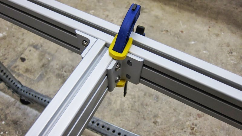
Starting with the two outer cross braces, finger tighten the attachment of the cross braces to the rail extrusion. Use soft jaw clamps to hold things in place, and make sure the clamp spans both pieces of extrusion. If you make the distance between cross braces consistent, programming and attaching a spoil board (one of the last steps) will be much easier.


At this point square and level the machine base. Make adjustments as needed and start tightening the machine base (and the leg kit if applicable). Measure diagonally to confirm squareness, make sure the legs are plumb and the surface is level. If you built a custom leg kit you might need to shim the machine base level. You may need to tighten, check, loosen, adjust, and tighten a couple of times, but getting things square and level now will make later assembly easier.


Section 3: V-Con Clamps and Rails

Now that your base frame is together, you can begin installing the V-Con linear motion components.


Time Saving Tip (TST) - Pre assembling the V-Con clamps will make installation faster. You can start on one side and slide them in from the end.


Space the V-Con Clamps out evenly along the X rails. If you align the V-Con clamp centered on the cross braces, it will make spoil board installation much faster. You can locate the cross braces even though you won’t be able to see them under the spoil board.


Next, install the 1018 Steel Flatbar. Make sure the CRS Flatbar is completely seated before tightening the set screws. Your rubber mallet and bar clamps will work well for this. Next, tighten the set screws for the steel to the V-Cons, then tighten the V-cons to the Extrusion Rail.


Section 4: Install the Gear Rack

(TST) - Pre install the hardware in the PRO Gear Rack and slide it in the end of the extrusion. Gear teeth should be facing down.


The Gear Rack is not centered on the extrusion. It should be spaced 1” from the edge of the Extrusion Rail on the back side of the machine. You can see this highlighted in green.


Section 5: Riser Assembly CRP420-00

There is both a right and a left riser assembly, these are mirror images of one another. Pre assemble these on your workbench. Occasionally there might be some powdercoat that builds up in the threads, this will be evident if your bolt binds as you are trying to thread it in.. If this happens use a M8 Tap for clearing the threads. If you don't have a tap use a couple drops of vegetable oil and an M8 bolt will also work.


When you install the Riser Assembly onto the rails, you will need to make some adjustments to the V-Con Clamps so you have even tension along the entire length of the rail. Make sure each riser rolls smoothly independently. It is best to tighten the sled assembly as it saddles a V-Con Clamp, this will prevent you from flexing the steel rail as you set the tension. When everything is rolling smoothly, tighten all 3 connection points on the sled assembly (two bolts holding the sled to the plate, and the jam nut on the adjuster bracket).


Now is a good time to install the 4 X Bumper plates, this will prevent your riser from rolling off the end unexpectedly. We will use the plate to align the gantry, so leave the rubber bumpers off until you have completely assembled your gantry.

Align the front of the extrusion to the front Gusset.


Your riser extrusion should be aligned like this:


Use your Bar clamps, and lock each riser against the X bumper.


The PRO riser assembly includes some extra hardware for easy connection of the rack and pinion drives. Each side has an M8 x 10mm hex head bolt and washers to connect the tension bracket, and a 90mm tension bolt. Proper use of these components is outlined in Section 8: Rack and Pinion Drives.


Section 6: Gantry CRP430-00

Set your gantry on top of the risers, and hand tighten all of the gussets. The gantry is slightly longer than the distance between the outside of the riser extrusions . Try and center this overhang.


Make sure the gantry is square and level, and then tighten all of the fasteners.

(TST) - Pre assemble and slide your V-Con Clamps on from the end of the gantry.


Use bar clamps and rubber mallet to seat the Cold Roll Steel into the V-Con Clamps. Like before, tighten the setscrews to the steel, making sure the steel is completely seated in the V-Con. Then tighten the V-Con to the extrusion.


Install the gantry gear rack like the others, pre installing the t-nuts and sliding in from one end. The gear rack should be installed with the fasteners in the t-slot towards the rear of the gantry, with the teeth facing towards the front. Looking down on the gantry your gear rack should face down, and be spaced 4” from the right side.


CRP432-00 Carriage Assembly


This sub-assembly can be pre-assembled prior to installation on the machine. Pre assemble components to the Gantry interface plate as shown.


When you install the Back gantry support bracket, make sure to only hand tighten the 4 socket head screws on the back side. These will be tightened after the system is aligned on the rails.


Once this subsystem is assembled, it can be installed on the machine, and the tension sleds can be adjusted. First tighten the sled assembly on the Gantry interface plate (CRP430-01, which is part of the CRP432-00 assembly), then tighten the sled on the Back gantry support bracket, again tightening over a V-Con clamp.


Confirm all 6 V Bearings are making smooth contact, then tighten down the sled connection screws, followed by the 4 socket screws holding the back gantry support bracket on.


Section 7: Z Axis Installation

Once the carriage assembly for the gantry is installed, the Z axis can be installed to the CRP430-01 plate using the 8 supplied M6 screws. Use a straight edge on one side of the plate to square the Z to the 430 plate.


Section 8: Rack and Pinion Drives

X Axis Rack and Pinion Drives

The rack and pinion drives can now be installed on the risers.

Nema 23:
Nema 34:


See the PRO rack and pinion instructions for specifics on assembling the R&P drives:

www.cncrouterparts.com/pro-rp-instructions-p-220.html


Once the drives are assembled, these can be mounted to the R&P attachment bracket.


Note the use of the M8 x 90mm hex bolt in place of the standard tension bolt – this makes for easier tension adjustment on the 420 assembly. Additionally, the tension bracket for the R&P unit is mounted to the CRP420-04 plate with a short M8 hex bolt and washer to avoid interference with the V-rollers on the back side of the plate.
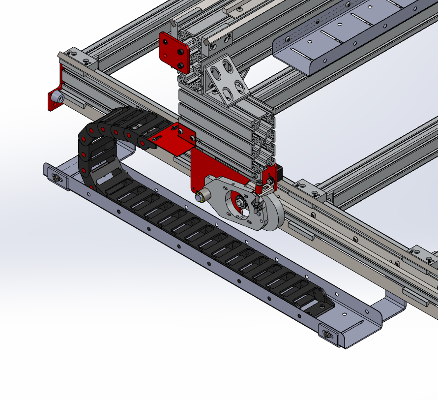


Y Axis Rack and Pinion Drives

The rack and pinion drive for the Y axis is mounted on top of the gantry, as seen below. This unit does not require the rack and pinion tension bracket, but instead makes use of the CRP430-03 back gantry support bracket to apply tension.


New in: Instructions & Configuration

PRO Cable Track Installation Instructions

$
0
0
PRO Cable Track Installation Instructions


Part 1: Trays and Brackets

  1. Loosely attach the cable tray brackets to the base table extrusion.

  2. Fasteners Used: (Double for 4896 and other large kits)

  • M8 x 16mm Button Head Cap Screw(4)
  • M8 Roll-in T-Nut(4)
Note: This part comes in two revisions, B and C. The B revision attaches to the inside face of the extrusion C revision attaches to the bottom face for compatability with later machine designs.


  • Place the cable tray(s) onto the cable tray brackets, and fasten.

  • Fasteners Used: (Double for 4896 and other large kits)

    • M8 x 12mm Button Head Cap Screw(6)
    • M8 Flange Nut(6)


  • Tighten the cable tray brackets to the extrusion.

  • Attach the CRP420-06 bracket to the riser extrusion.

  • Fasteners Used:

    • M8 x 16mm Button Head Cap Screw(4)
    • M8 Roll-in T-Nut(4)


  • Directly attach the remaining cable tray to the back of the gantry.

  • Fasteners Used:

    • M8 x 16mm Button Head Cap Screw(6)
    • M8 Roll-in T-Nut(6)


  • Attach the CRP440-10 bracket to the top of the CRP440-00 Ballscrew Z axis.

  • Fasteners Used (NEMA 23):

    • M6 x 16mm Socket Head Cap Screw(2)(Included in Ballscrew Z Hardware kit)

    Fasteners Used (NEMA 34):

    • M6 x 25mm Socket Head Cap Screw(2)
    • M6 Hex Jam Nut(2)


    Now you should have something like this.


    Part 2: Cables and cable track
    1. Attach one of the flat ends of the 75mm wide (the big one) to the table cable tray.

    2. Fasteners Used:

    • M6 x 12mm Socket Head Cap Screw(2)
    • M6 Jam Nut(2)
    • M6 Flat Washer(2)


  • Open the cable track using a twisting motion with a flat head screwdriver


  • Route the cables along the inside of the track.
  • Close the cable track.
  • Attach the other flat end of the cable track to the bottom of the CRP420-06 bracket.

  • Fasteners Used:

    • M6 x 12mm Socket Head Cap Screw(2)
    • M6 Jam Nut(2)
    • M6 Flat Washer(2)


  • Attach the flat end of the longer 50mm cable track to the gantry cable tray.
    (See Part 2: Step 1 image)

  • Fasteners Used:

    • M6 x 12mm Socket Head Cap Screw(2)
    • M6 Jam Nut(2)
    • M6 Flat Washer(2)

  • Open the cable track and route the gantry and Z-axis motor cables along the inside. The X' and the nearby sensor cable should not be routed through the cable track, and should instead either be routed through the middle of the gantry extrusion, or along the cable tray.
  • Close the cable track
  • Attach the hole end of the cable tray to the threaded hole on near the edge of the CRP430-03 bracket.

  • Fasteners Used:

    • M8 x 16mm Socket Head Cap Screw(1)


  • Attach one of the flat ends of the remaining cable track to the two tapped holes on the CRP430-03. Make sure the track is bending the right way!

  • Fasteners Used:

    • M6 x 12mm Socket Head Cap Screw(2)


  • Attach the other flat end to the holes on the CRP440-10 bracket.

  • Fasteners Used:

    • M6 x 12mm Socket Head Cap Screw(2)


  • Open the cable track.


  • Route the Z motor cable through the cable track. The easiest way to do this will be to start from the bottom of the cable track, and close the cable track one flange at a time as you route the cable.
  • Go cut somet hing!

  • New in: Instructions & Configuration

    Ethernet Smoothstepper Installation guide for Nema 34

    Viewing all 329 articles
    Browse latest View live