Quantcast
Channel: Avid CNC
Viewing all articles
Browse latest Browse all 334

PRO Cable Track Installation Instructions

$
0
0
PRO Cable Track Installation Instructions


Part 1: Trays and Brackets

  1. Loosely attach the cable tray brackets to the base table extrusion.

  2. Fasteners Used: (Double for 4896 and other large kits)

  • M8 x 16mm Button Head Cap Screw(4)
  • M8 Roll-in T-Nut(4)
Note: This part comes in two revisions, B and C. The B revision attaches to the inside face of the extrusion C revision attaches to the bottom face for compatability with later machine designs.


  • Place the cable tray(s) onto the cable tray brackets, and fasten.

  • Fasteners Used: (Double for 4896 and other large kits)

    • M8 x 12mm Button Head Cap Screw(6)
    • M8 Flange Nut(6)


  • Tighten the cable tray brackets to the extrusion.

  • Attach the CRP420-06 bracket to the riser extrusion.

  • Fasteners Used:

    • M8 x 16mm Button Head Cap Screw(4)
    • M8 Roll-in T-Nut(4)


  • Directly attach the remaining cable tray to the back of the gantry.

  • Fasteners Used:

    • M8 x 16mm Button Head Cap Screw(6)
    • M8 Roll-in T-Nut(6)


  • Attach the CRP440-10 bracket to the top of the CRP440-00 Ballscrew Z axis.

  • Fasteners Used (NEMA 23):

    • M6 x 16mm Socket Head Cap Screw(2)(Included in Ballscrew Z Hardware kit)

    Fasteners Used (NEMA 34):

    • M6 x 25mm Socket Head Cap Screw(2)
    • M6 Hex Jam Nut(2)


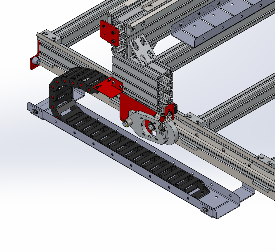
    Now you should have something like this.


    Part 2: Cables and cable track
    1. Attach one of the flat ends of the 75mm wide (the big one) to the table cable tray.

    2. Fasteners Used:

    • M6 x 12mm Socket Head Cap Screw(2)
    • M6 Jam Nut(2)
    • M6 Flat Washer(2)


  • Open the cable track using a twisting motion with a flat head screwdriver


  • Route the cables along the inside of the track.
  • Close the cable track.
  • Attach the other flat end of the cable track to the bottom of the CRP420-06 bracket.

  • Fasteners Used:

    • M6 x 12mm Socket Head Cap Screw(2)
    • M6 Jam Nut(2)
    • M6 Flat Washer(2)


  • Attach the flat end of the longer 50mm cable track to the gantry cable tray.
    (See Part 2: Step 1 image)

  • Fasteners Used:

    • M6 x 12mm Socket Head Cap Screw(2)
    • M6 Jam Nut(2)
    • M6 Flat Washer(2)

  • Open the cable track and route the gantry and Z-axis motor cables along the inside. The X' and the nearby sensor cable should not be routed through the cable track, and should instead either be routed through the middle of the gantry extrusion, or along the cable tray.
  • Close the cable track
  • Attach the hole end of the cable tray to the threaded hole on near the edge of the CRP430-03 bracket.

  • Fasteners Used:

    • M8 x 16mm Socket Head Cap Screw(1)


  • Attach one of the flat ends of the remaining cable track to the two tapped holes on the CRP430-03. Make sure the track is bending the right way!

  • Fasteners Used:

    • M6 x 12mm Socket Head Cap Screw(2)


  • Attach the other flat end to the holes on the CRP440-10 bracket.

  • Fasteners Used:

    • M6 x 12mm Socket Head Cap Screw(2)


  • Open the cable track.


  • Route the Z motor cable through the cable track. The easiest way to do this will be to start from the bottom of the cable track, and close the cable track one flange at a time as you route the cable.
  • Go cut somet hing!

  • New in: Instructions & Configuration

    Viewing all articles
    Browse latest Browse all 334

    Trending Articles